In 1913, the Rennsteig-Frauenwald Kleinbahn (KRF) was opened. From 1912 onwards, the Gottfried Lindner A.G. wagon factory in Ammendorf near Halle (which later became the well-known VEB Waggonbau Ammendorf) supplied several narrow-gauge railways with four-axle combined passenger, mail, and baggage coaches with eight upholstered 2nd-class seats and 40 wooden 3rd-class seats. The first of these coaches was delivered to the Rennsteig-Frauenwald Kleinbahn (KRF), and another went to the Obereichsfelder Silberhausen-Hüpstedt Kleinbahn (OEK), which opened around the same time. Two more coaches were delivered to the KyffhäuserKleinbahn (Artern-Berga-Kelbra) around 1916. These were equipped with toilets due to the significantly longer route. The Genthin Kleinbahn also received a coach of this type. From the 2nd-class compartment, passengers could access the luggage compartment via a side corridor past the mail compartment, and from there into the seating and cargo compartments. The mail and luggage compartments had sliding doors on both sides. The carriages had a steel undercarriage. A wooden car body rested on this, clad in sheet metal on the outside.Heating was provided by steam from the locomotive, and the mail compartment also had a stove with a smoke vent on the roof. Originally, the carriage had vacuum brakes and was lit by kerosene. Thus, the carriage combined everything necessary under one roof.
In the 1930s, the KRF had its carriage converted to electric lighting; a little later, the vacuum brakes were replaced by compressed air brakes. Thus, the KRF carriage survived World War II and was taken over by the Deutsche Reichsbahn (DR) in 1949. Shortly thereafter, the carriage underwent fundamental modifications: the previously open platforms were replaced by closed ones, and the mail compartment and the luggage compartment were combined. The shortage of materials during those years is likely due to the fact that only one revolving door was installed on the side where the platform was in Allzuhah, and two of different widths on the other side.
Thus, the car remained in use on its home line until the end of the 1950s. Around 1960, it is said to have been "transferred" to the (Meiningen-) Rentwertshausen - Römhild line. Its further whereabouts are unknown. The OEK car was converted to a pure passenger car, but retained its open platforms. In this form, it is being gradually "rebuilt" to its original form by the Friends of the Halle-Hettstedt Railway to commemorate the now-vanished Ammendorf vehicle-building tradition.
Another description
BCPwPost4i were four-axle passenger coaches, independently developed by the G. Lindner wagon factory in Halle/Saale. They were used by several provincial Saxon Kleinbahns, such as the Rennsteig-Frauenwald Kleinbahn. These vehicles were capable of handling the entire traffic volume of the Kleinbahns equipped with them. They had open platforms on both sides. The Kyffhäuser Kleinbahn also acquired similar vehicles in 1915, two of which were used by the Deutsche Reichsbahn during the course of nationalization, initially with the running numbers 99151Erf and 99152 Erf, later 210-404 and 210-405. In 1960, one such coach was seen at Leipzig Central Station, being transported to its home station after being repaired. At that time, the open platforms were fitted with a protective wall extending up to the roof, including a door to the transition facility.At [www.verlag-rockstuhl.de], you have to go up and there's a search function where you can type in Laura. The book "From the History of the Rennsteig-Frauenwald Kleinbahn 1913-1965 / The Rennsteig Railway / The Laura" by Günter Fromm appears. The cover of this book shows such a model, pulled by a locomotive. In the book, Knipping, Andreas; Quill, Klaus-Peter et al.: The "6000 Series" of the German Reichsbahn. Routes and vehicles of the expropriated private and Kleinbahns in the GDR. (EK-Verlag, Freiburg: on page 347, there is a beautiful photo of such a representative, which had a protective wall extending up to the roof, including a door to the transition facility, on the open platforms. Waggonfabrik G. Lindner also produced several such carriages, both in the same and slightly modified form, for Merseburg Kleinbahns. The carriages had a 2nd-class compartment at one end, adjoining a mail and baggage compartment, each with sliding side doors. The other part of the carriage was furnished as a 3rd-class compartment. I hope you enjoy this article. I would be happy to receive any questions, suggestions, additions, criticism, or suggestions for improvement.
On the KRF
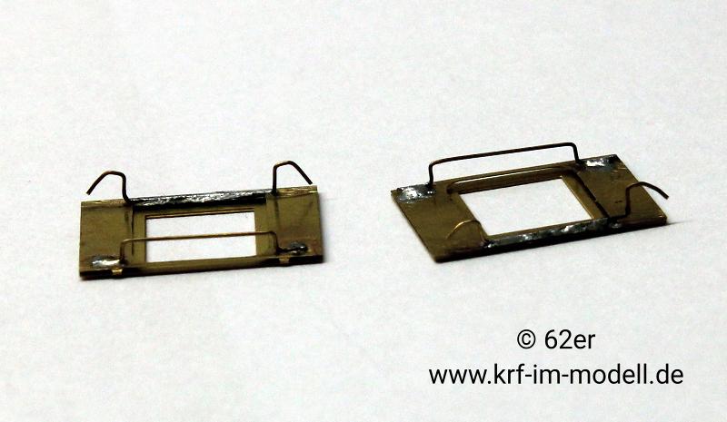
Note the variations
The model directly above has the same configuration of double doors as seen in the image of the accident in 02/56
Handy Links
Additional bits needed
OBK coupling (Michael Weinert / H0fine #100)
Flange for the OBK (Michael Weinert / H0fine #112)
Spirit stain (H0fine #400) Basswood strips (H0fine #605)
Signal holder (Weinert 8265)
Suction air hoses (Weinert 8285)
Grab bar holder (Weinert 8465)
Spring buffer, double-slotted (Weinert 8608)
Handbrake crank (Weinert 9267)
0.3 mm brass wire (Weinert 9300)
0.3 mm nickel silver wire (Weinert 9309)
Method
A few words about the kit itself. Mr. Schlosser provides a very stable envelope in which three brass etching plates are located to 0,3mm thickness. These are clearly structured in chassis and frame, car body as well as roof and interior design, as can be seen here:

Furthermore, the H0fine wheels according to RP25 is equipped with the width Code 88 as well as short coupling scenery and various small parts. However, in my kit model railway coupling as well as a buffer were missing, which, however, should be replaced by the fine coupling and spring buffer from the very beginning. Mr. Schlosser offered me a corresponding discount for compensation. Finally, a detailed building instruction was also included in pictures and letters, general kit and assembly instructions as well as decals and window film.
But enough of the preface. Now the construction is finally being started. After carefully reading and understanding the building instructions as well as all the enclosed information, I started with the bogies, as provided by Mr Schlosser. After the first bogie was discharged from the etching plate, the cut surfaces were cleaned with a file and a first bend were made.

Before the front and back of the bogie panel could be folded to each other, the axle bearings made of plastic had to be glued. After that it went quickly with fold and continue to stick.
And because it was so nice, the second bogie continued immediately. The first test mountings with the supplied wheels (diameter 10.5mm, axle length 24.75 mm) revealed that the bogies in the area of the brake shoes as well as the bogie coverings are too flexible for my taste. I decided to stiffen the bogie a little by connecting the opposite brake shoes by a 0.3mm nickel silver wire. Furthermore, between bogie trim and brake shoes, I filled the gap with 0.5 polysterol and connected everything with glue. The two bogies then look like this after the assembly:
So far for today. I hope that I have aroused your interest in some of you and would be happy to hear questions, comments and comments on your part.
Please note, The soldering does not work for two reasons - but at my car. I have already glued the bogies together. And much more importantly: the bogie panels are doubling and the axle bearings are located between the sheets. They cannot be glued in according to the construction after soldering the bogie panels.
Part Two
In the last days I was able to spare a few hours for the car construction. The next stage was the vehicle frame. I gradually bent the long beams with a bending aid due to the length and always alternately front and rear half. And despite several reading of the instructions, I had started to bend the first long-beam wrongly around. So I had to turn the two upper steps back to the post and packing compartments. These are then, as was to be expected, broken off. However, they could be glued back up quite well.
This was followed by further detailing the frame on the bottom. So I mounted the frame profiles and cross bracing. The latter sit with slight pressing between the longitudinal beams and do not actually have to be glued at all. After that, the brake cylinders and boilers were glued in. I have stiffened the step carriers at their base by a 0.3mm strong brass wire, because I did not want to leave the kicks simply made of brass sheet.
The finished mounted frame then looks like this:
Then followed the two stages, each of which consists of an etching part. So it was only called bending and gluing and they were almost finished. I have supplemented them with suction hoses and a handbrake crank from Weinert. The flat etching parts did not quite promise me in this case. But see for yourself:
I am only just considering how I can now mount the flange for the H0fine coupling.
WARNING: My model has closed ends NOT verandas 
This is how the car has so far looked when the condition is plugged together:
As already written, I do not want to mount flat tin steps on the car. First I thought I could make the kicks entirely of lime wood strips. This proved to be extremely impractical. On the one hand, the 0.3mm veneer wood is very vulnerable to breakdown and on the other hand the positioning aids, which were intended for the kicks, were lacking. So I glued the lower sheet metal for the kick (which should be doubled according to the instructions) with the wooden strips. Then I cut the wood according to the tread plate and polished. Here very much you have an appearance for the luggage or luggage. Posted compartment (left) and a set of kicks for the stage:
WARNING:- Please do hesitate before using wood for the steps, metal strip is more robust
However, I will only mount the steps after painting. In addition, I have yet to make attempts to color the wooden parts. I have planned dark wood stains for this.
That was so far for today.
Part three
In the last few weeks I have done many large and small things about the car. On the one hand, I glued the car body from head and side walls as well as the roof frame. The biggle cases helped a lot with a precise fit seat during assembly. These were naturally sanded after gluing.
I also assembled the roof. This only forms the wood panelling from the inside and can therefore be easily shaped with the help of the roof chairs. To obtain a closed surface, a "non-absorbing paper, e.g. a catalogue page" should be glued to the roof. In my opinion, however, the catalogue paper is far too smooth. Here you can see the roof before the edges were cleaned with a nail scissors.
So I decided to use a location pulp as a candy imitation. I have already found this tip several times on the internet. I am curious about how it looks painted. Unfortunately, you don't see too much of it in the photo.
Then I treated the wooden steps in color. For this purpose, I used the spirit stain of 400 from H0fine and the boards in several passes were painted with a brush and wiped them again with a tissue shortly afterwards.
Last but not least, I could not help myself in between and put the car body and the roof on the wheels. In the meantime, it is now more clear where the journey goes with the kit.
It is now time to get on with the build and although I mainly worked on my modules, there was still a lot to do on the lower-way car.
Unfortunately, the next report will then have to be somewhat to come, as the painting work is coming up next. But always beautiful in turn:
First I prepared the roof for holding smoke extraction and lamp fans. For this purpose, the openings were drilled up to 1mm or 2mm. After that I glued the trigger and the fan.
The remaining small parts, such as the window frames, train routing signs and compartments, were separated and cleaned. However, I did not like the etched curtains of the windows from the second grade, so I want to try to present them with fabric.
So I removed the metal curtains from the windows and soldered curtain rails to the back of the windows with 0.3 brass wire (wine 9300). As a potential curtain material, I bought a silk cloth as well as various ribbons from the local craft shop.
Furthermore, I refined the kit with a few Weinert (see list) cast parts. On the one hand, I soldered signal holders (8264) to the roof supports and replaced the flat handle bars on the entry platforms with grip bar holders (8465) and 0.3mm nickel wire (9309). For the holders, the openings in the car body had to be divised to 0.6mm.
I had ignored the problem with the couplings for a long time. Flanges with a rectangular coupling opening were already present in the buffer planks, which, however, did not appeal to me very much. Since I want to install the finer OBK coupling by Michael Weinert (H0fine à 100), the use of the matching flange was also available as a 3D printing part (H0fine à 112). However, this had to change the rectangular opening into a round. However, drilling is eliminated here. Here a suggestion from a work colleague helped me further: grinding. So after the attached flange imitation had been filed, I prepared a drilling pad with appropriate depressions and swallows the opening with a diamond cutter.
For the double slotted spring buffer (Wine 8608) I descended the corresponding openings with a ball milling machine by hand to ensure easier slip. However, since the buffers pierced and the step holder are close to the buffer finrenal, I drilled corresponding openings by hand into the holders. This was done in several stages from 0.4mm over 0.7mm and 1.0mm up to 1.2mm. After everything has been checked for a suitable seat, I glued the platforms with the car frame and glued the coupling flanges.
In the meantime, you can already see clearly what the car should look like.
Unfortunately the author died before posting further updates
----------------------------------------------------------------------------------------------------------
Below is the original text as translated, it differs slightly from the above.
Before the front and back of the bogie panel could be folded together, the plastic axle bearings had to be glued in. After that, the folding and gluing continued quickly.
And because it was so beautiful, I immediately moved on to the second bogie. The first test assemblies with the included wheels (10.5 mm diameter, 24.75 mm axle length) revealed that the bogies were too flexible for my taste in the area of both the brake shoes and the bogie covers. I decided to stiffen the bogie a bit by connecting the opposite brake shoes with 0.3 mm nickel silver wire. I also filled the gap between the bogie cover and the brake shoes with 0.5 mm polystyrene and bonded everything together with glue. The two bogies look like this after assembly:
Over the last few days, I've been able to spare a few hours for the vehicle construction. So, the next step was the vehicle frame. Due to their length, I used a bending aid to bend the idler beams in stages, alternating the front and rear halves. And despite reading the instructions several times, I started bending the first idler beam the wrong way around. So I had to bend back the two upper steps to the mail and parcel compartments. These broke off in the process, as expected. But they were easy to glue back on. Further detailing of the frame followed on the underside. I mounted the frame profiles and cross braces. The latter sit between the idler beams with a slight compression and actually don't need to be glued at all. Then the brake cylinders and air chambers were glued in place. I stiffened the base of the step supports with 0.3 mm thick brass wire, as I didn't want to leave the steps simply made of brass sheet. The fully assembled frame looks like this:
Next came the two stages, each consisting of a single etched part. So it was just a matter of bending and gluing, and they were almost finished. I added suction hoses and a Weinert handbrake crank. The flat etched parts didn't quite appeal to me in this case. But see for yourself:
I'm just trying to figure out how to mount the flange for the H0fine coupling. This is what the car looks like so far, assembled:
As I wrote before, I don't want to install flat metal steps on the car. At first, I thought I could make the steps entirely from linden wood strips. This proved extremely impractical. Firstly, the 0.3mm veneer is very prone to breakage, and secondly, the positioning aids provided for the steps were missing. So, I glued the wooden strips to the lower sheet metal for the step (which was supposed to be doubled according to the instructions). I then cut and filed the wood to fit the step plate. Here you can see a step for the luggage or mail compartment (left) and a set of steps for the platform:
I won't install the steps until after the paint is applied. I also need to experiment with staining the wooden parts. I've planned to use a dark wood stain for that.
Over the past few weeks, I've done a lot of work on the car, both big and small. First, I glued the car body, consisting of the front and side walls, and the roof frame. The bending tabs, with their precise fit, were very helpful during assembly. These were, of course, sanded down after gluing.
I also assembled the roof. This simply replicates the wood paneling from the inside and can therefore be easily shaped using the roof ribs. To create a sealed surface, a piece of non-absorbent paper, such as a catalog page, should be glued to the roof. In my opinion, however, the catalog paper is far too smooth. Here you can see the roof before the edges were neatly trimmed with nail scissors.
So I decided to use a layer of cellulose as a canvas imitation. I've found this tip several times online. I'm curious to see how it looks when painted. Unfortunately, you can't see much of it in the photo.
Then I treated the running boards with color. I used H0fine's #400 spirit stain, applying several coats of glaze with a brush, and then wiping them off with a tissue.
First, I prepared the roof to accommodate the smoke vent and lamp fans. For this, the openings were drilled out to 1 mm and 2 mm, respectively. Then I glued the vent and the fans in place.
The remaining small parts, such as the window frames, train route signs, and compartment walls, were removed and cleaned up. However, I didn't like the etched curtains on the second-class windows, so I wanted to try to recreate them with fabric. So, I removed the metal curtains from the windows and soldered curtain rods to the backs of the windows using 0.3 mm brass wire (Weinert 9300). As potential curtain material, I bought a silk scarf and various ribbons from the local craft store.
I also refined the kit with a few Weinert cast parts. First, I soldered signal brackets (8264) to the roof supports and replaced the flat grab bars on the boarding platforms with grab bar brackets (8465) and 0.3 mm nickel silver wire (9309). The openings in the car body had to be widened to 0.6 mm to accommodate the brackets.
Then I'd been putting off the problem with the couplers for a long time. The buffer beams already had flanges with rectangular coupling openings, but I wasn't particularly keen on them. Since I wanted to install Michael Weinert's finer OBK coupler (H0fine #100) in a flexible manner, using the matching flange as a 3D-printed part (H0fine #112) was also a good option. However, this meant changing the rectangular opening to a round one. Drilling was out of the question here. A suggestion from a colleague helped me out: grinding. So, after filing the etched flange imitation flat, I prepared a drilling base with the appropriate recesses and ground the opening round with a diamond grinder.
For the double-slotted spring buffers (Weinert 8608), I reamed the corresponding holes by hand with a ball-end mill to ensure an easier fit. However, since the buffers pierce through and the step holders are located close behind the buffer beam, I drilled corresponding holes in the holders by hand. This was done in several steps from 0.4 mm to 0.7 mm to 1.0 mm to 1.2 mm. After checking everything for a proper fit, I glued the platforms to the car frame and glued in the coupling flanges.


No comments:
Post a Comment
Spam and anonymous comments never get published but it does make me laugh!
And whilst your reading this, everything I post is subject to copyright.